



G GCSE Apps

GCSE Science

P2 Electricity

11 subtopics in this section

Circuit symbols, charge and current

Definition

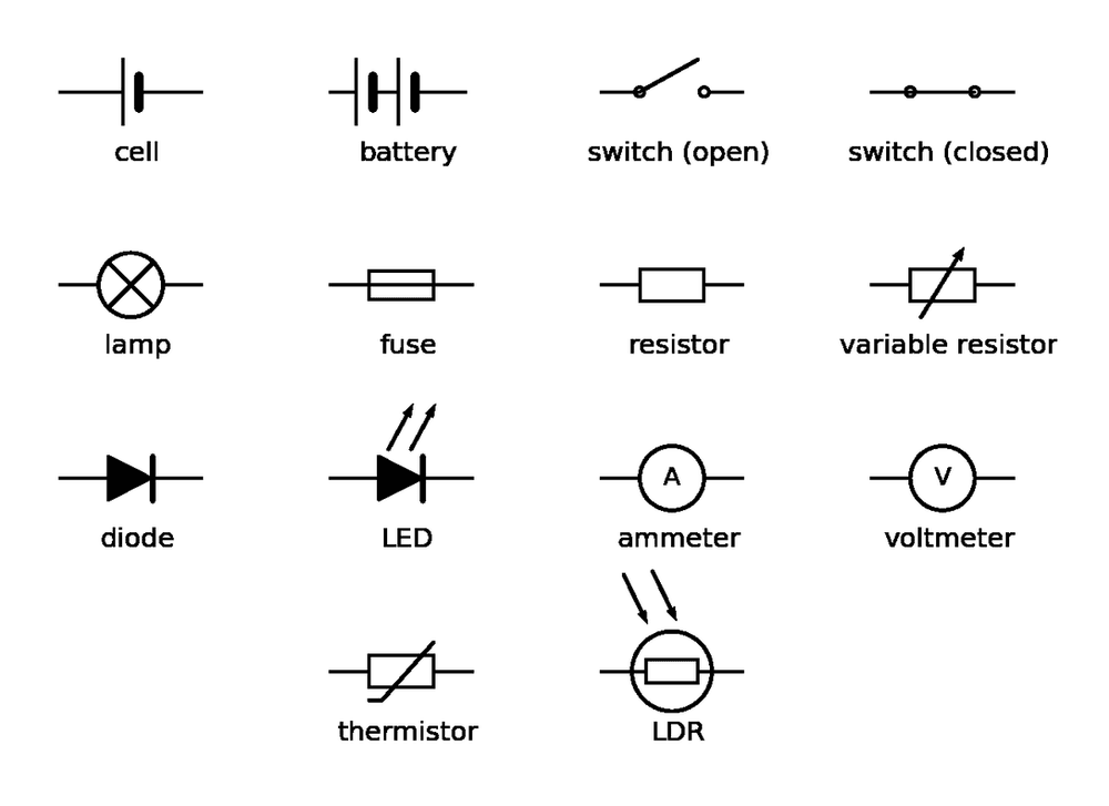
Circuit diagrams use standard symbols to show how components are connected.

Electric current is the rate of flow of electrical charge. Charge is measured in coulombs (C) and current in amperes (A). In a single closed loop, the current has the same value at every point. In solid metal conductors, this current is a flow of electrons.

Charge only flows round a closed loop that contains a source of potential difference, such as a cell or battery. Opening a switch breaks the loop and stops the current everywhere in it.

Method

Charge flow: Q = I t, so charge flow = current × time.

Time must be in seconds (s). To convert minutes to seconds, multiply by 60.

Current must be in amperes (A). To convert milliamperes (mA) to A, divide by 1000.

Diagram
phys circuit symbols

Note

The standard symbols. A battery is two or more cells joined together. An ammeter is connected in series with a component; a voltmeter is connected in parallel across it.

Example

A current of 2.5 A flows through a bulb for 4 minutes. How much charge flows through the bulb?

Solution

Convert time to seconds: 4 × 60 = 240 s

Charge flow = 2.5 × 240 = 600 C

Example

A charge of 180 C flows through a circuit in 2 minutes. What is the current?

Solution

Convert time to seconds: 2 × 60 = 120 s

Rearrange Q = I t to find current: I = Q ÷ t

Current = 180 ÷ 120 = 1.5 A

Tips/hints

Current is not used up by components: the current flowing into a lamp equals the current flowing out of it.

A cell is a single unit; a battery is two or more cells joined together.

Convert time to seconds and milliamperes to amperes before using Q = I t.
Current, potential difference and resistance

Definition

The current through a component depends on both its resistance and the potential difference across it.

For a given potential difference, a bigger resistance makes it harder for charge to flow, so it gives a smaller current.

Method

Potential difference: V = I R, so potential difference = current × resistance.

Rearranged: I = V ÷ R and R = V ÷ I.

Potential difference is in volts (V), current in amperes (A) and resistance in ohms (Ω).

Diagram

phys ammeter voltmeter circuit

Note

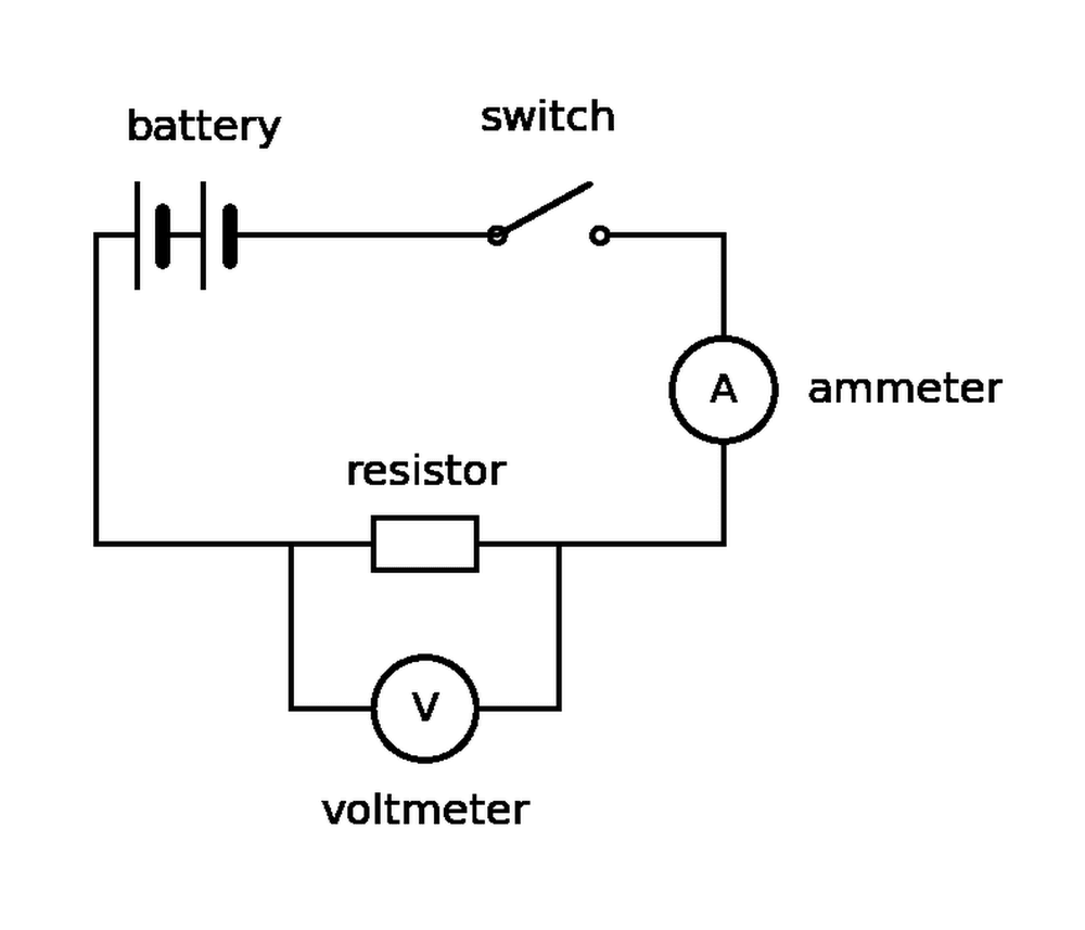
The ammeter is in series with the resistor and measures the current through it. The voltmeter is connected in parallel across the resistor and measures the potential difference across it. Resistance = potential difference ÷ current.

Example

A resistor on a circuit board has a resistance of 3.3 kΩ and a current of 2.0 mA flows through it. What is the potential difference across the resistor?

Solution

Convert the units first: 3.3 kΩ = 3300 Ω and 2.0 mA = 0.0020 A.

Use V = I R: 0.0020 × 3300 = 6.6 V.

Tips/hints

Most lost marks come from forgetting to convert units like milliamperes (mA) to amperes (A), or kilohms (kΩ) to ohms (Ω).

Remember the circuit rules: ammeter in series, voltmeter in parallel.

If the potential difference across a fixed resistor is doubled, the current through it will also double, because they are directly proportional.

Resistors and I–V characteristics

Definition

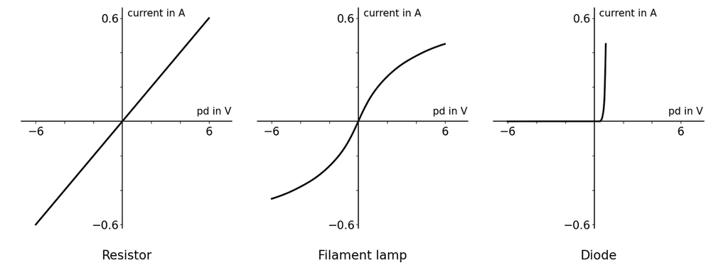
An ohmic conductor (like a fixed resistor at constant temperature) has a constant resistance. Current is directly proportional to potential difference, so its I–V graph is a straight line through the origin.

A filament lamp gets hotter as current increases, increasing its resistance. The I–V graph curves and gets less steep at higher potential differences.

A diode only lets current flow in one direction. It has a very high resistance in the reverse direction. In the forward direction, current flows once the potential difference passes a small value.

A thermistor's resistance decreases as temperature increases (used in thermostats). An LDR's resistance decreases as light intensity increases (used in automatic lights).

Method

To find the resistance at a point on an I–V graph, read the potential difference and the current at that point and use R = V ÷ I (resistance = potential difference ÷ current). Do not use the gradient of the graph.

Diagram

phys iv characteristics

Note

The resistor's graph is a straight line through the origin, so its resistance is constant. The lamp's graph bends over as the filament heats up. The diode only conducts for a small positive potential difference.

Example

A filament lamp has a current of 0.16 A at 1.0 V and 0.38 A at 4.0 V. How does its resistance change?

Solution

At 1.0 V: R = 1.0 ÷ 0.16 = 6.3 Ω

At 4.0 V: R = 4.0 ÷ 0.38 = 10.5 Ω

The resistance increases because the filament is hotter.

Tips/hints

Read V and I off the axes and divide V by I; dividing I by V gives a value that is far too small.

Thermistor: hotter means lower resistance. LDR: brighter means lower resistance.

A curved I–V graph means the resistance is changing, so the component is non-linear.

Series and parallel circuits

Definition

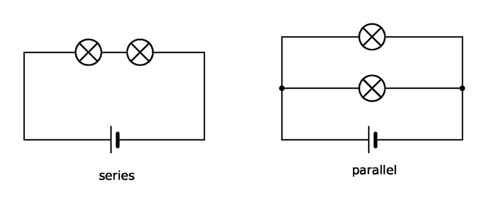
Components can be joined in series (one loop) or in parallel (separate branches). House lights are wired in parallel so each can be switched on its own, and one failing does not turn off the others.

Method

Series: Current is the same everywhere. The supply potential difference is shared (the component potential differences add up to the supply). Total resistance is the sum of the individual resistances: Rtotal = R1 + R2. Adding a resistor in series increases total resistance as current must pass through both.

Parallel: Each branch receives the full supply potential difference. Total current leaving the supply is the sum of the branch currents. Adding a resistor in parallel decreases total resistance because it provides an extra path, increasing the total current from the supply.

Diagram

phys series parallel lamps

Note

Series (left): one loop, so the same current passes through both lamps and they share the cell's potential difference. Parallel (right): each lamp is on its own branch across the cell.

Example

A 6.0 V battery is connected in series with a 2.0 Ω resistor and a 4.0 Ω resistor. What is the potential difference across the 4.0 Ω resistor?

Solution

Total resistance: 2.0 + 4.0 = 6.0 Ω.

Current (the same everywhere in series): I = V ÷ R = 6.0 ÷ 6.0 = 1.0 A.

Potential difference across the 4.0 Ω resistor: V = I R = 1.0 × 4.0 = 4.0 V (the other 2.0 V is across the 2.0 Ω resistor).

Tips/hints

In series, the potential difference is shared in proportion to the resistances, not equally (unless the resistances are equal).

Current is not used up: in a series circuit it is the same everywhere.

Two resistors in parallel have a total resistance less than the smaller one. You do not need to calculate it.

Mains electricity

Definition

UK mains electricity is an alternating potential difference (ac) supply with a frequency of 50 Hz and a potential difference of about 230 V.

An alternating potential difference repeatedly reverses direction, meaning the current constantly changes direction. A direct potential difference (dc), like from a battery, acts in one direction only.

Method

Most appliances connect to the mains using a three-core cable:

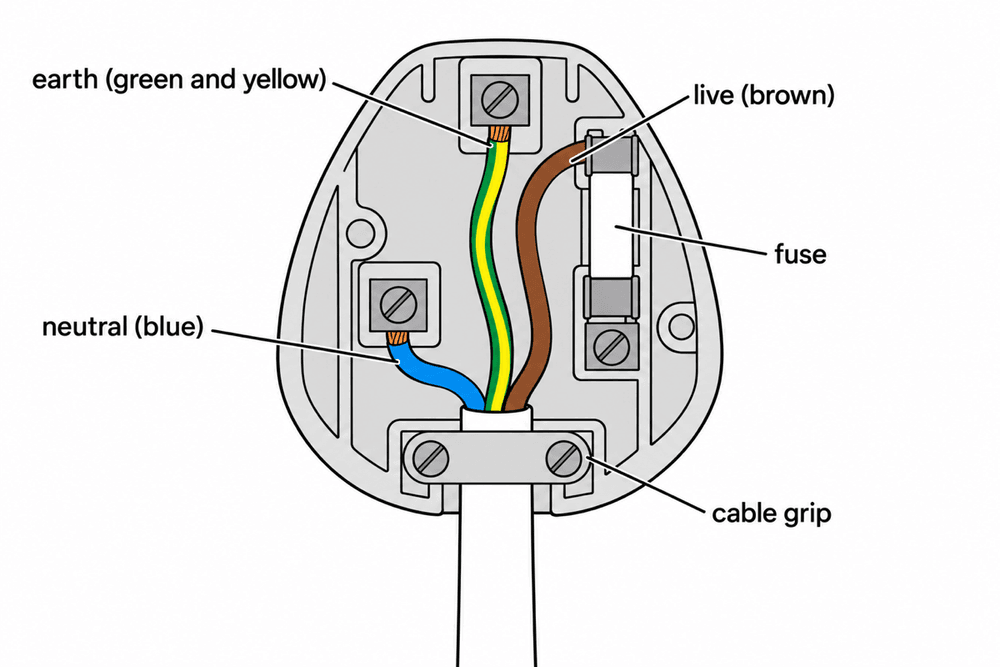
Live wire (brown): carries the alternating potential difference from the supply (about 230 V).

Neutral wire (blue): completes the circuit back to the supply and is at, or close to, 0 V.

Earth wire (green and yellow stripes): a safety wire at 0 V that stops the appliance casing becoming live. It only carries a current if there is a fault.

Diagram

phys three pin plug

Note

Inside a UK plug: brown live wire to the fuse and live pin, blue neutral wire to the neutral pin, green and yellow earth wire to the earth pin. The cable grip holds the outer cable.

Example

A bicycle lamp runs from a 6 V battery. A table lamp runs from the mains. Compare the current in the two lamps.

Solution

The battery gives a direct potential difference, so the current in the bicycle lamp flows in one direction only (dc).

The mains gives an alternating potential difference of about 230 V at 50 Hz, so the current in the table lamp keeps reversing direction (ac).

Tips/hints

The neutral wire does carry a current when the appliance is on; it completes the circuit.

The earth wire is a safety wire: it carries no current in normal use.

A live wire is dangerous even when a switch is open: touching it connects 230 V to earth through your body, so a large current can flow.

Electrical power

Definition

The power of a device is the rate at which it transfers energy. It tells you the energy transferred per second and is measured in watts (W). One watt is equal to one joule per second.

The electrical power of a circuit component depends on both the potential difference across it and the current flowing through it.

Method

Power from current and potential difference: P = V I, so power = potential difference × current.

Power from current and resistance: P = I2 R, so power = current² × resistance. Only the current is squared.

Power is in W, potential difference in V, current in A, and resistance in Ω.

Example

A television has a power of 46 W and runs from the 230 V mains. What current flows through it?

Solution

Rearrange P = V I to find the current: I = P ÷ V.

I = 46 ÷ 230 = 0.20 A.

Tips/hints

Check your units before calculating: convert kilowatts (kW) to watts, and milliamperes (mA) to amperes.

When using P = I2 R, remember to square the current before multiplying by the resistance.

When rearranging to find the current from power and resistance, do not forget the final square root.

If the current through a fixed resistor doubles, its power becomes four times as large because power depends on the current squared.

Energy transfers in appliances

Definition

Electrical appliances are designed to transfer energy. For example, a washing machine transfers energy from the ac mains to the kinetic energy store of its electric motor, while an electric shower transfers energy to the thermal store of its heating element.

Whenever charge flows in a circuit, work is done, which means energy is transferred.

Method

The amount of energy an appliance transfers depends on its power and how long it is switched on. A higher-power appliance transfers more energy in a given time.

You can calculate the energy transferred with:

E = P t, so energy transferred = power × time.

E = Q V, so energy transferred = charge flow × potential difference.

Power must be in watts (W), time in seconds (s), charge in coulombs (C), potential difference in volts (V) and energy in joules (J).

Example

An electric car battery supplies a potential difference of 400 V. It moves 30 000 C of charge through the motor. How much energy is transferred?

Solution

Use E = Q V (energy transferred = charge flow × potential difference):

E = 30 000 × 400 = 12 000 000 J (or 12 MJ).

Tips/hints

Always convert time in minutes or hours into seconds before using E = P t.

Convert kilowatts (kW) into watts (W) by multiplying by 1000.

Current is not used up as it flows around a circuit; instead, the charge flowing does work to transfer energy to the appliance.

Some questions require two steps: you might need to find the charge flow using Q = I t or power using P = V I before you can calculate the energy transferred.

The National Grid

Definition

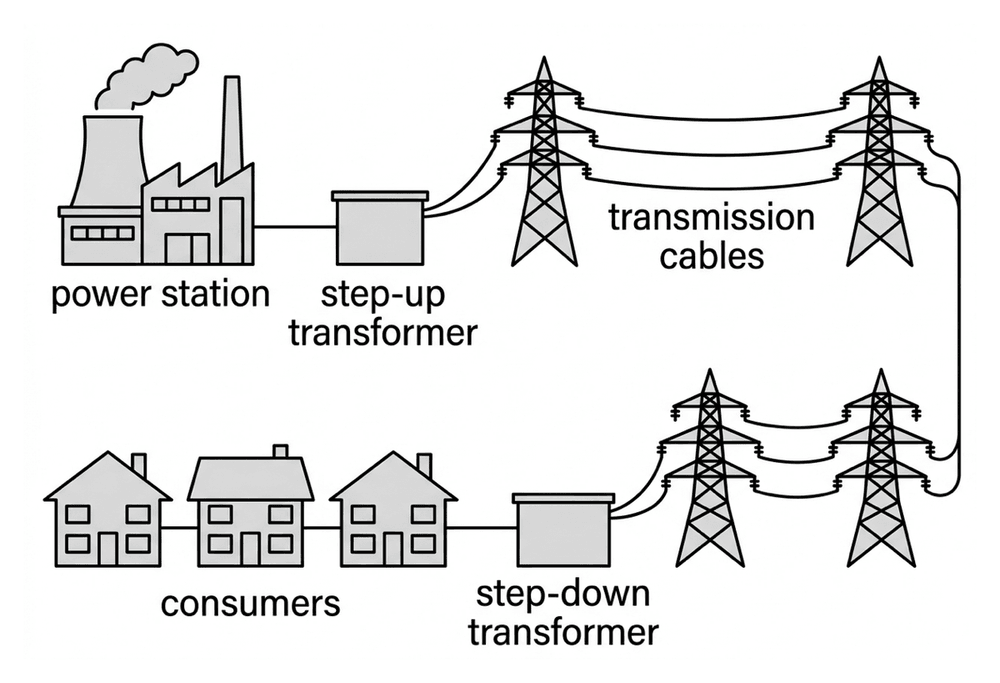
The National Grid is the nationwide network of cables and transformers that connects power stations to homes, offices and factories. It transfers electrical power from power stations to consumers.

Method

Step-up transformers are placed next to power stations. They increase the potential difference (to hundreds of thousands of volts) for the transmission cables. Step-down transformers are placed near consumers. They reduce the potential difference to a much lower, safer value (about 230 V for homes).

Using a high potential difference makes the National Grid efficient. For a given power, a higher potential difference means a smaller current (P = V I, power = potential difference × current).

A smaller current means much less heating of the transmission cables, so less energy is dissipated to the surroundings. The power lost is proportional to the current squared (P = I2 R, power = current² × resistance).

Diagram

phys national grid

Note

Step-up transformers next to the power station raise the potential difference for the transmission cables; step-down transformers near consumers lower it again.

Example

A transmission cable transfers 5 000 000 W of electrical power at a potential difference of 400 000 V. What is the current in the cable?

Solution

Use P = V I (power = potential difference × current).

Rearrange to find current: I = P ÷ V

I = 5 000 000 ÷ 400 000 = 12.5 A

Tips/hints

Step-up transformers increase the potential difference, but they do not increase the power or energy.

A high potential difference reduces the current and minimises energy lost as heat; it does not make the electricity move faster.

Remember that step-down transformers are near the consumers, not at the power station.

Halving the current quarters the power lost in the cables, because the power lost depends on the current squared.

Transformer equation (Higher)

Definition

An ideal transformer is 100% efficient: no energy is dissipated to the surroundings, so the power in the primary coil equals the power in the secondary coil.

The National Grid uses step-up transformers to increase potential difference for transmission. For the same power, this lowers the current. A smaller current reduces energy wasted heating the cables, making transmission more efficient. Step-down transformers then reduce potential difference to safer levels.

Method

Transformer equation: Vp × Ip = Vs × Is

V is potential difference in volts (V) and I is current in amperes (A). The subscript 'p' is for primary and 's' is for secondary.

Example

A step-up transformer has 25 V across its primary coil and a primary current of 8.0 A. The potential difference across the secondary coil is 400 V. Assuming it is ideal, what is the secondary current?

Solution

Use Vp × Ip = Vs × Is: 25 × 8.0 = 400 × Is

200 = 400 × Is

Is = 200 ÷ 400 = 0.50 A. The potential difference went up 16 times, so the current went down 16 times.

Tips/hints

Convert prefixes like kV to volts by multiplying by 1000 before you calculate.

The side with the higher potential difference always has the lower current. If your step-up transformer calculation gives a larger primary current, you rearranged incorrectly.

Transformers change potential difference and current to keep the transmission power the same but reduce heating in the cables.

Required practical: Resistance

Overview

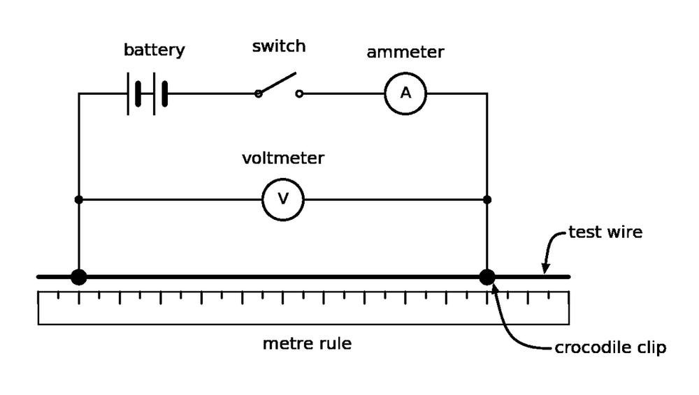
This practical investigates two factors that affect resistance: the length of a wire (at constant temperature), and combining resistors in series and in parallel.

Method

1. Tape a thin test wire along a metre rule.

2. Connect a battery, switch, ammeter and the wire in series, using crocodile clips on the wire.

3. Connect a voltmeter across the wire between the two clips.

4. Set the clips 10 cm apart, close the switch, read the current and potential difference, then open the switch.

5. Repeat in 10 cm steps up to 100 cm and plot resistance against length.

6. Measure two resistors in series and then in parallel in the same way.

Knowledge Required

Equation: R = V ÷ I, so resistance = potential difference ÷ current. The independent variable is the wire length. The dependent variable is the resistance. Control variables include the wire's material, thickness, and temperature.

Note

Hazard: The wire gets hot. Do not touch it while current flows.

Diagram

phys resistance wire circuit

Note

The ammeter is in series with the test wire. The voltmeter is connected across the wire between the crocodile clips, so it measures the potential difference across the length being tested.

Tips/hints

Switch off between readings and use a low current, so the wire does not heat up and raise its resistance.

A straight line that misses the origin shows a systematic (zero) error, often contact resistance at the clips.

Two resistors in series have a larger total resistance than either one; in parallel, a smaller total resistance than either one.

Required practical: I–V characteristics

Overview

This practical investigates how the current through a component depends on the potential difference across it. You test a fixed resistor, a filament lamp and a diode.

Method

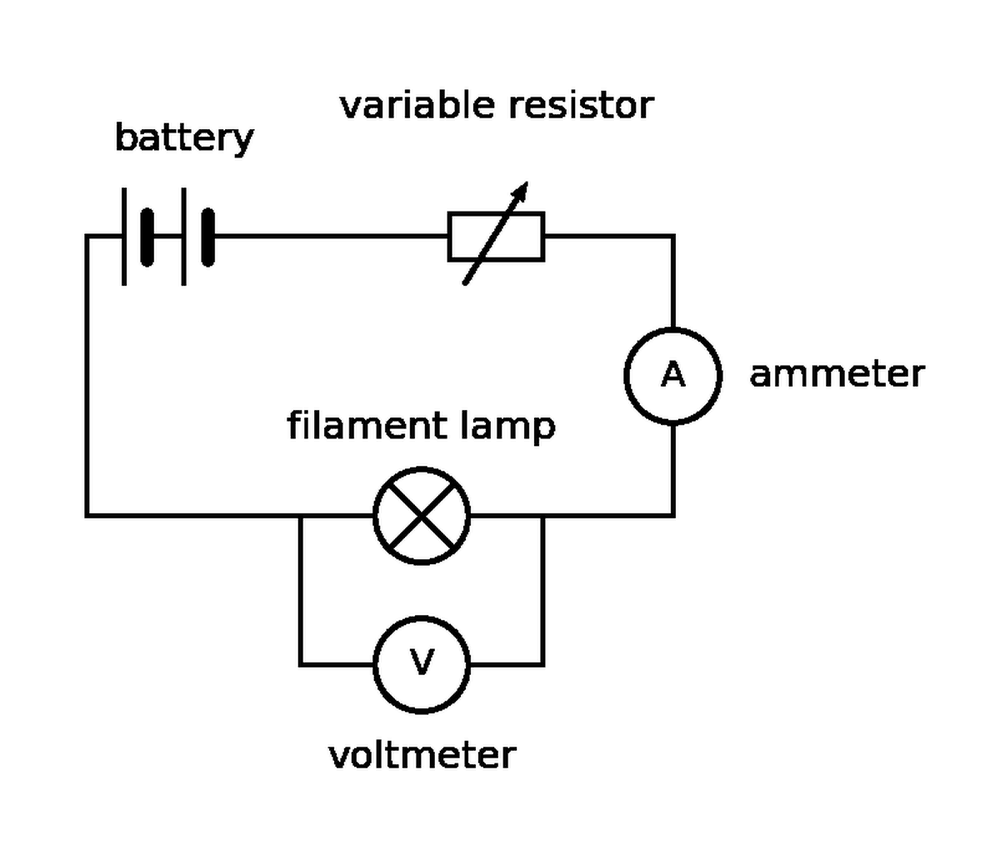
1. Set up the circuit with the power supply, variable resistor, ammeter and test component in series. Connect the voltmeter in parallel across the test component.

2. Use the variable resistor to adjust the potential difference across the component.

3. Record the potential difference and the current. Repeat to take about 10 pairs of readings.

4. Reverse the connections to the power supply. This reverses the current, giving negative readings.

5. Record negative readings for potential difference and current.

6. Plot a graph of current on the y-axis against potential difference on the x-axis. This is an I–V characteristic.

Knowledge Required

Independent variable: potential difference across the component.

Dependent variable: current through the component.

Control variable: the temperature of the component (for the fixed resistor).

Apparatus: a power supply, a variable resistor (to change the potential difference), an ammeter in series, a voltmeter in parallel, and the test component.

Note

Hazards: the lamp and resistor can get hot; switch off between readings and let them cool.

Use a protective resistor in series with a diode to limit the current.

Diagram

phys iv practical circuit

Note

The battery, variable resistor, ammeter and filament lamp are in series. The voltmeter is connected across the lamp only. Changing the variable resistor changes the potential difference across the lamp.

Tips/hints

Resistor (constant temperature): straight line through the origin. Filament lamp: a curve that flattens as it heats. Diode: almost no current in reverse, rising steeply above about 0.6 V.

Resistance at any point: R = V ÷ I; for a curve it is different at each point.

Take extra readings where the graph bends, and repeat readings to reduce random errors.

Test yourself on this topic

Try the free quiz with worked solutions.

Start quiz →

Get GCSE Science

Full notes, full question bank, offline.